Case Studies

Ignite_energy_References

Bahrain City Centre

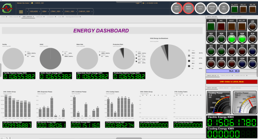
• Location: Manama, Bahrain

• Client: ENOVA /MAF

• Main Vendor: SCHNIDER/ AVEVA/ HONEYWELL

• Building Type: Shopping Mall and 2 attached Hotels

Built Up Area: 4,800,000 sq ft

• Building Opening: 2008

System Overview

  • Bahrain City Centre central cooling plant is located in three story energy Centre, which is situated at North East corner of the building. The Plant includes:
  • 7 Nos centrifugal water-cooled Trane chillers located at ground floors,
  • 7 Nos primary chilled water pumps located at basement,
  • 7 Nos condenser water pumps located at 2nd floor,
  • 8 Nos cooling tower at the 3rd floor roof of energy center.
  • Many FAHUs, AHUs and FCUs on the air side(1100+).

Customer Challenges & Requirements

  • Price sensitive
  • Multi-Protocol Communication
    • Modbus  TCP & RTU
    • BACnet  IP & MS/TP
    • LonWorks
  • Optimize No. Of chillers running to satisfy load demand and minimize the electrical energy consumption .
  • Optimize the pump speed and water flow to satisfy load demand and minimize the electrical energy consumption.

Issues & Findings

  1. Water flow balance issue for all chillers “evaporators and condensers” and cooling towers. Some units have overflow while others have underflow.
  2. Constant cooling tower speed control
  3. Constant condenser pump speed control
  4. Hybrid plant configuration, variable primary flow and secondary decoupled configurations exist in one plant.
  5. High pressure fluctuations on the primary circuit caused by the improper plant configuration and make it impossible to control the primary pump speed. That made the primary VFDs useless
  6.  The hotel circuits always have low flow issue because they are the only two circuits that has no secondary pumps compare to the other 14 circuits.
  7. On the air side there are 1100 units all equipped with control valves but no balancing mechanism
  8. Most of the air side units has low flow issues because of the improper water flow balance
  9. No proper fresh air and air quality control
  10. Negative pressure inside the building
  11. The existing chiller plant manager used conventional delta T demand control.

Our Solution

  1. Active flow balance for chiller “evaporators, condensers” and cooling towers. That include supply and installation of new actuators, pressure sensors, and flow meters. This is to guarantee every unit will get its right share of water flow at any time.
  2. Changing existing plant configuration from hybrid to variable primary- variable secondary by design, supply, installation, and commissioning of 2 new secondary pump sets for hotel 1 and hotel 2. This is to guarantee the proper hydraulic separation in the system and to ensure pressure stability on the primary circuits.
  3. Design configuration and installation of SESLADO-AEMS system with associated algorithms, Optimal Secondary Flow, Optimal Balance Flow, Optimal Heat Reject. Etc.
  4. Supply, Installation, & Commissioning of VFDs, Air quality Sensors, Air pressure sensors for FAHUs to ensure the proper pressure and air quality control inside the building.
  5. Implementing central flow balance algorithm for all air side units to ensure the chilled water flow balance throughout the circuit.

Results

  1. Instead of 6 chillers and 6 pumps at full speed, only 4 chillers and 4 pumps at 90% load were required at the building peak demand.
  2. Operator friendly HMI plant view that gives the operator the full monitoring and supervising view of the entire HVAC.
  3. Advanced Energy, power, and efficiency dashboard.

Lulu Hypermarket - AlQusais

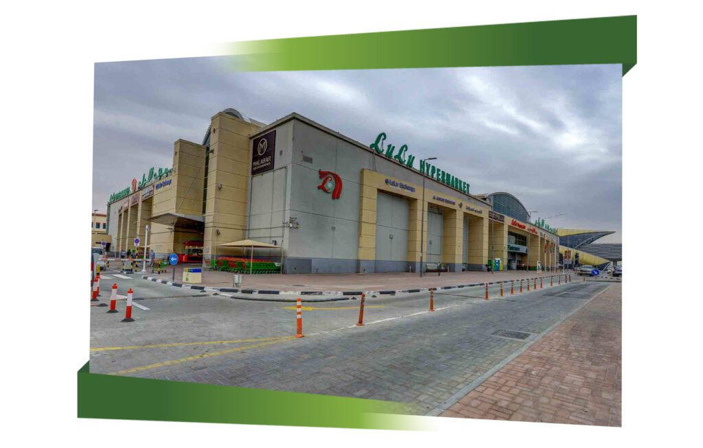
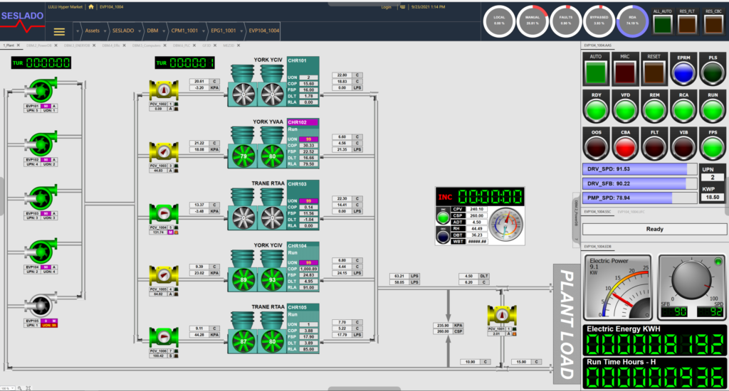
• Location: Dubai, UAE

• Client: LuLu Group International

• Main Vendor: SCHNIDER, HONEYWELL

• Building Type: Hypermarket – G+2

Built Up Area: 222,000 ft²

• Building Opening: 2000

ISSUES & FINDINGS

  1. Five air-cooled chillers, Five constant primary pumps, and 3 way valve air side system.
  2. No motorized control / isolation valves on chiller. All chillers are always fully open.
  3. No bypass / decoupler line existing in the plant.
  4. No control system. Full manual operation.
  5. Many hotspots on the air side.
  6. System plant is fully loaded (5 chillers and 5 pumps) most of the time. consuming maximum power without achieving the target building air quality.

Our Solution

  1. Changing plant configuration from constant primary to variable primary flow
  2. VFDs for the pumps
  3. Motorized control valves for the chillers
  4. Differential pressure, temperature, and flow sensors
  5. Installation of bypass line with motorized control valve.
  6. Two-way PICV for the air side units.
  7. DDC Controllers for the air side units.
  8. SESLADO-AEMS for the chiller plant and air side.
  9. Installation testing and commissioning result.

RESULTS

  1. Instead of 5 chillers and 5 pumps at full speed, only 3 chillers and 3 pumps at 80% load were required at the building peak demand.
  2. Operator friendly HMI plant view that gives the operator the full monitoring and supervising view of the entire HVAC.
  3. Advanced Energy, power, and efficiency dashboard.
SESLADO_Lulu_hupermarket_
× How can I help you?